Saturday, 21 December 2013

Final Big Day of Bachelor of Engineering Technology Students

Before i brief further i want to Thanks to God, family, my supervisor n friends for the prayers, support n guide.Finally done with my own heart beat rate measurement device interface with smartphone via wireless technology. Below is my picture waiting for the lecturer to access me.


The comment from the lecturer is i have to include more analysis or results of my project, such as the analysis or prove that the distance of the bluetooth, difference between the real PPG devices with the TCRT1000 which is optical sensor and Bluetooth signals analysis. I will keep continue with the results and analysis to improve the performance of the results. I have also tabulated table of the results of heartbeat rate of other students, which is as below:

Students
Frequency Average (Hz)
Heart Beat Rate (BPM)
A
1.205
72.3
B
1.316
78.96
C
1.923
115.38
D
769.2m
46.152

The heart beat rate of the students is as below:


Results from Student A (1.205Hz)

Results from Student B (1.316Hz)

Results from Student C (1.923Hz)

Results from Student D (769.2mHz)

The lecturer also comment that, i should also include the students health condition with the results obtained from the students. This i take as improvement of the devices. Further more, the recommendations to improve the device is to change the wireless technology that used. I suggest that, replacing the bluetooth to GSM module so that, it can transmit the data anywhere. 

That's all for now. I will keep updating and research to improve the heart beat device that using wireless technology to transmit the data as to help the community to get the healthier life and easier life. Bye bye for now, and i have to get ready for my final exam. See all you again..Bye

Saturday, 14 December 2013

Getting Ready for Industrial Day

Hai everybody,

I am very excited about the presentation day and i have to refresh back and study about my project which is heart beat monitoring with smartphone via bluetooth. I have to study about how the system works. From the TCRT1000 sensor, process by 2 signal conditioning and transmit it to the smartphone via bluetooth. This week, i will also prepare the casing of the project and final testing of the circuit which is shown in Figure below.


As shown on Figure, the heart beat rate device monitor with LCD and smartphone via bluetooth is done and successful. I am ready for the presentation day. See you all there...

Friday, 6 December 2013

Ready for Final Year Project Presention

The requirement for UniKL BMI on presentation day is a poster about the project. The poster should include as below:


  • Objectives
  • Abstract
  • Methodology
  • Diagram
  • Analysis
  • Results
  • Conclusion
I have make my own poster, which i used power point to do it, and adjusting the paper layout. The step are shown on Figure below.


The full poster of my project that already converted to the pdf format is as below.


Done with the poster, and i'm ready with the presentation. Bye for now...

Saturday, 30 November 2013

Ready for Final Year Project Report

This is almost comes to the end of the Final Year Project, where the project is almost done and we have to do the report about the project. The report should have:


  • Abstract - Summary of research objective, research scope of study and methodology and expected findings
  • Introduction - Overview of project and objectives. Problems identification and the significant of the study.
  • Literature review - The theoretical study and/or recent study from journal and/or relevant resources.
  • Material and Methodology - Materials and methods must support scope of studies. Analysis/ hardware design/case study must be relevant to the objectives.
  • Results/Discussion - Data/graph/calculation/results presentation support the objectives of the study. Data, calculations and derived results are clearly presented. Data accuracy and precision be addressed. Discussion must relate to theory/literature, comparison be made between experimental results and theoretical/predicted/reported values
  • Recommendation and Conclusion - Overall conclusion must be clearly stated along with recommendations for future work.
  • Project Report format/organization - Project report written and organize according to the required format. Content is well organized and coherent.
After the report has been done, hard cover for the report must be include. It is requirement of the UniKL BMI as the report has been completed. The report then submitted to the library of UniKL BMI, which also can be view here http://ir.unikl.edu.my/jspui/handle/123456789/530

That's all by now, next week will be the presentation of the all Final Year Project. See you guys there..

Saturday, 23 November 2013

Testing and Troubleshooting the Wireless Bluetooth PPG

This is difficult task of the week, because it is require more patience and applying all the electrical and electronic plus with communication knowledge to get its done. Before i'm going to explain the real circuit of my PPG, i would like you all to know that, the first circuit of the PPG is not functioning. Previous testing was done and there's a lot of noise and resonant occur as shown on Figure. The figure was taken from the google, just for the example of the noise resonant.


Resonance of a circuit involving capacitors and inductors occurs because the collapsing magnetic field of the inductor generates an electric current in its windings that charges the capacitor, and then the discharging capacitor provides an electric current that builds the magnetic field in the inductor. This process is repeated continually. An analogy is a mechanical pendulum.
At resonance, the series impedance of the two elements is at a minimum and the parallel impedance is at maximum. Resonance is used for tuning and filtering, because it occurs at a particular frequency for given values of inductance and capacitance. It can be detrimental to the operation of communications circuits by causing unwanted sustained and transient oscillations that may cause noise, signal distortion, and damage to circuit elements. This is might because of my circuit not functioning. Plus, the previous PPG was damage because of the over-current injected to the PPG. 
So, for my last minute plan, i have to use other PPG or heartbeat device detector. I get the second PPG circuit from http://embedded-lab.com/blog/?p=5508. I construct the circuit from the web from the beginning by constructing the PCB layout and lastly, testing the circuit. Except that, i add so that i can monitor the heart beat rate. The result is as below.
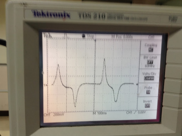
The circuits consist of 3; 5V voltage regulator with LCD, PPG circuit and Arduino circuit. After the circuit successful get the results that almost accurate, i'm doing the analysis by view the signal by using the oscilloscope. The results that i obtained is as below:

For this circuit, it is without Bluetooth Bee to transmit the data to the smartphone wirelessly. Figure above shows the circuit is operating and display on oscilloscope. The A0 pin of Arduino are connected to the oscilloscope to get the output of the heart beat rate. The output voltage waveform is produce by the heart beat rate circuit. The differences between two beats from the peak value will then measured in term of frequency. From the Figure above, the results obtained is 1.266Hz, then multiply it by 60 to get the Beat Per Minute (BPM) value, which is equal to 75.96 BPM.

I'm also taking the results for the First and Second Stage of signal conditioning. Just want to know how the waveform looks like. Below are the results:
First Stage Signal Conditioning
Second Stage Signal Conditioning

As shown on above, there are difference waveforms which is the waveform at first stage is not detail as second stage of signal conditioning. Then the buffer amplifier is used to transfer a voltage from a first circuit, having a high output impedance level, to a second circuit with a low input impedance level. The interposed buffer amplifier prevents the second circuit from loading the first circuit unacceptably and interfering with its desired operation. In the ideal voltage buffer in the diagram, the input resistance is infinite, the output resistance zero (impedance of an ideal voltage source is zero). Other properties of the ideal buffer are: perfect linearity, regardless of signal amplitudes; and instant output response, regardless of the speed of the input signal.

After the results for the analysis have been done, i'm proceed with interfacing the PPG circuit to the smartphone via bluetooth. I'm using the previous program that i've already post on previous blog. The result is as below:
As you can see, the results of the heart beat rate is appear on the LCD and smartphone. The data will keep transmitting to the smartphone via Bluetooth as long as Bluetooth is ON. The Bluetooth bee must be set to Trans mode so that the data can be transmit. The application Bluetooth SPP.apk which available on PlayStore android should be download as the platform of the device.

I know the circuit is quite messy, and now i have to think the casing of my PPG. See you guys next week.. :)

Wednesday, 13 November 2013

Bluetooth Programming and Testing

Hai Everybody,

This week I'm gonna research how to write programs so that my device can interface with smartphone bluetooth to send data. First of all, i'm gonna used Cytron Bluetooth Bee as shown on Figure.


As shown on Figure, there are Arduino Uno R3 that attached with Xbee Shielding, and top of it is Bluetooth Bee. There are also shows how to connect with the 16x2  LCD and connecting to the PPG circuit. The  Bluetooth  bee  is  supplied  by  3.3V  from  the  Arduino,  while  the  Arduino  is supplied by 5V from the USB port of the computer or from the 5V voltage regulator. To program the ATmega328 of the Arduino, Arduino IDE must be download, because it is the compiler of the system. Figure below shows the one of the screenshot of  the Arduino IDE compiler.


The  figure  above shows  the  Arduino  IDE  software  already  been  installed  on  the computer and it is connected to the COM3 of the computer USB port ready to be programmed.  Arduino  IDE  will  compile  the  sketch  and  upload  into  Arduino  UNO connected to your computer (if there is no error), further run the sketch on Arduino UNO. You will just have to wait until the message box say Upload Done and look at
the Arduino Uno. The red LED are always  blink at 1 second rate  when 5V is supplied to the Arduino. Figure below shows the Bluetooth Bee pin out.

To make sure the Bluetooth Bee is functioning well before proceed with the real program, i search on the Google the simple program. Just to make sure it can at least transmit any data to the smartphone. But first, i'm gonna use Bluetooth SPP.apk one of the applications that can be found on the Play Store of the Android phone. It is platform that can transmit or receive data from Bluetooth Bee. Below are the program that allow transmitting to the smartphone via bluetooth:

#include <AltSoftSerial.h>
#define rxPin 0
#define txPin 1

AltSoftSerial mySerial(rxPin, txPin);

void setup()
{
// define pin modes for tx, rx pins:
pinMode(rxPin, INPUT);
pinMode(txPin, OUTPUT);
mySerial.begin(9600);
Serial.begin(9600);
}
void loop(){
mySerial.print("BPM");
mySerial.print(BPM);
Serial.print("BPM=");
Serial.println(BPM);
delay(1000);
}
delay(80);
}

This program is successful, but i will show on the week that i will presentation day. See all of you there..

Friday, 8 November 2013

Arduino Uno R3 Programming and Testing

Hai everyone,

Until this week, i already did testing one by one of my circuit. Start from the 5V supply, to the LCD, to the Arduino Uno R3 and PPG circuit. As you can see figure below, there are the result.


It is not clear, the LCD printing some words which is "Heart Beat Rate BPM  = (love symbol). As you guys can see, my circuit is working, but now, i have some problem which is the output from the PPG is not appear at the LCD. Theres might be my programming or the circuit design. Still working on it. Wish me luck