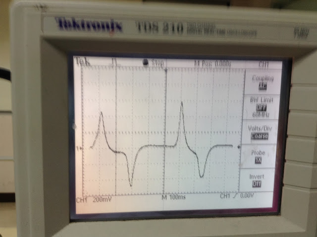
This is difficult task of the week, because it is require more patience and applying all the electrical and electronic plus with communication knowledge to get its done. Before i'm going to explain the real circuit of my PPG, i would like you all to know that, the first circuit of the PPG is not functioning. Previous testing was done and there's a lot of noise and resonant occur as shown on Figure. The figure was taken from the google, just for the example of the noise resonant.
Resonance of a circuit involving capacitors and inductors occurs
because the collapsing magnetic field of the inductor generates an electric current
in its windings that charges the capacitor, and then the discharging capacitor
provides an electric current that builds the magnetic field in the inductor.
This process is repeated continually. An analogy is a mechanical pendulum.
At resonance, the series impedance of the
two elements is at a minimum and the parallel impedance is at maximum.
Resonance is used for tuning and filtering, because it occurs at a
particular frequency for given values
of inductance and capacitance. It can be detrimental to the
operation of communications circuits by causing unwanted sustained
and transient oscillations that may cause noise, signal distortion,
and damage to circuit elements. This is might because of my circuit not
functioning. Plus, the previous PPG was damage because of the over-current
injected to the PPG.
So, for my last minute plan, i have to use other PPG
or heartbeat device detector. I get the second PPG circuit from http://embedded-lab.com/blog/?p=5508.
I construct the circuit from the web from the beginning by constructing the PCB
layout and lastly, testing the circuit. Except that, i add so that i can
monitor the heart beat rate. The result is as below.
The circuits consist of 3; 5V voltage regulator with
LCD, PPG circuit and Arduino circuit. After the circuit successful get the
results that almost accurate, i'm doing the analysis by view the signal by
using the oscilloscope. The results that i obtained is as below:
For this circuit, it is without Bluetooth Bee to transmit the data to the smartphone wirelessly. Figure above shows the circuit is operating and display on oscilloscope. The A0 pin of Arduino are connected to the oscilloscope to get the output of the heart beat rate. The output voltage waveform is produce by the heart beat rate circuit. The differences between two beats from the peak value will then measured in term of frequency. From the Figure above, the results obtained is 1.266Hz, then multiply it by 60 to get the Beat Per Minute (BPM) value, which is equal to 75.96 BPM.
I'm also taking the results for the First and Second Stage of signal conditioning. Just want to know how the waveform looks like. Below are the results:

First Stage Signal Conditioning
Second Stage Signal Conditioning
As shown on above, there are difference waveforms which is the waveform at first stage is not detail as second stage of signal conditioning. Then the buffer amplifier is used to transfer a voltage from a first circuit, having a high output impedance level, to a second circuit with a low input impedance level. The interposed buffer amplifier prevents the second circuit from loading the first circuit unacceptably and interfering with its desired operation. In the ideal voltage buffer in the diagram, the input resistance is infinite, the output resistance zero (impedance of an ideal voltage source is zero). Other properties of the ideal buffer are: perfect linearity, regardless of signal amplitudes; and instant output response, regardless of the speed of the input signal.
After the results for the analysis have been done, i'm proceed with interfacing the PPG circuit to the smartphone via bluetooth. I'm using the previous program that i've already post on previous blog. The result is as below:
As you can see, the results of the heart beat rate is appear on the LCD and smartphone. The data will keep transmitting to the smartphone via Bluetooth as long as Bluetooth is ON. The Bluetooth bee must be set to Trans mode so that the data can be transmit. The application Bluetooth SPP.apk which available on PlayStore android should be download as the platform of the device.
I know the circuit is quite messy, and now i have to think the casing of my PPG. See you guys next week.. :)


.jpg)
